LC3 Instruction Set Architecture
09 Jun 2020Having learned about datapath and microcode, we can now treat the internal machine instruction flow of LC3 as a blackbox and abstract up one level to talk about Instruction Set Architecture (ISA), which specifies everything in the computer that is available to a programmer when writing programsin machine language.
The ISA specifies the memory organization, register set, and instruction set, including the opcodes, data types, and addressing modes of the instructions in the instruction set.
Memory Organization
In LC3, the address space is 216 = 65536. The unique address locations are 0 - 65535, or x0000 - xFFFF. The addressability is 16 bits, or a word, and it is strictly word addressable, not byte addressable (cannot access a byte, unlike Intel x86 or ARM).
The avaialbe addresses for users programs live in memory x3000 - x FDFF inclusive.
ISA Design Philosophy
Two major design philosophies: CISC (Complex Instruction Set Computer) and RISC (Reduced Instruction Set Computer).
In CISC, one machine code instruction can do a very complicated, high level task that people use often, like resizing an array. Examples of CISC are Intel x86, DEC VAX, IBM Z-series.
RISC, on the other hand, has a very limited vocabulary. If a programmer wants to resize an array in a RISC machine, the programmer needs to write many lines of code to perform the resizing, which is harder to accomplish, but the advantage is that it exposes as much instruction to the compiler as possible to make optimization easier. Examples of RISC are ARM, MIPS, PowerPC, and our very own LC3.
Opcode
LC3 allocates 4 bits out of the 16-bit instruction addressability for opcode. There are 24 = 16 different possible opcode instructions (Technically 15 opcodes because number 13 is reserved).
Assembly Language
Assembly langauge is the human-readable representation of the machine managuge. Assembly and machine langauge instructions have one-to-one correspondence.
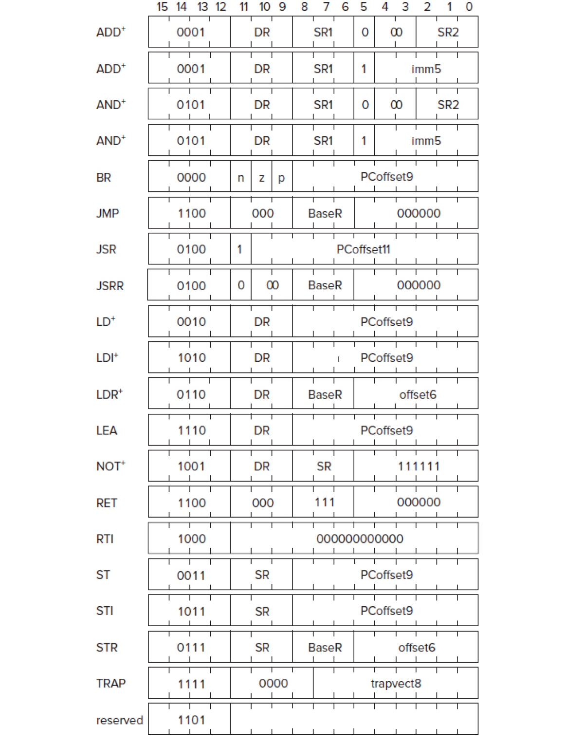
Figure 1 shows the correspondence of Assembly Langugage Instruciton and Machine Language Instruction, and further breaks down the Machine Instruction into opcode.
Execute State for OPERATION Instructions
Operate Instructions all take 1 clock cycle in the execute phase. They are: NOT, ADD, and AND
NOT
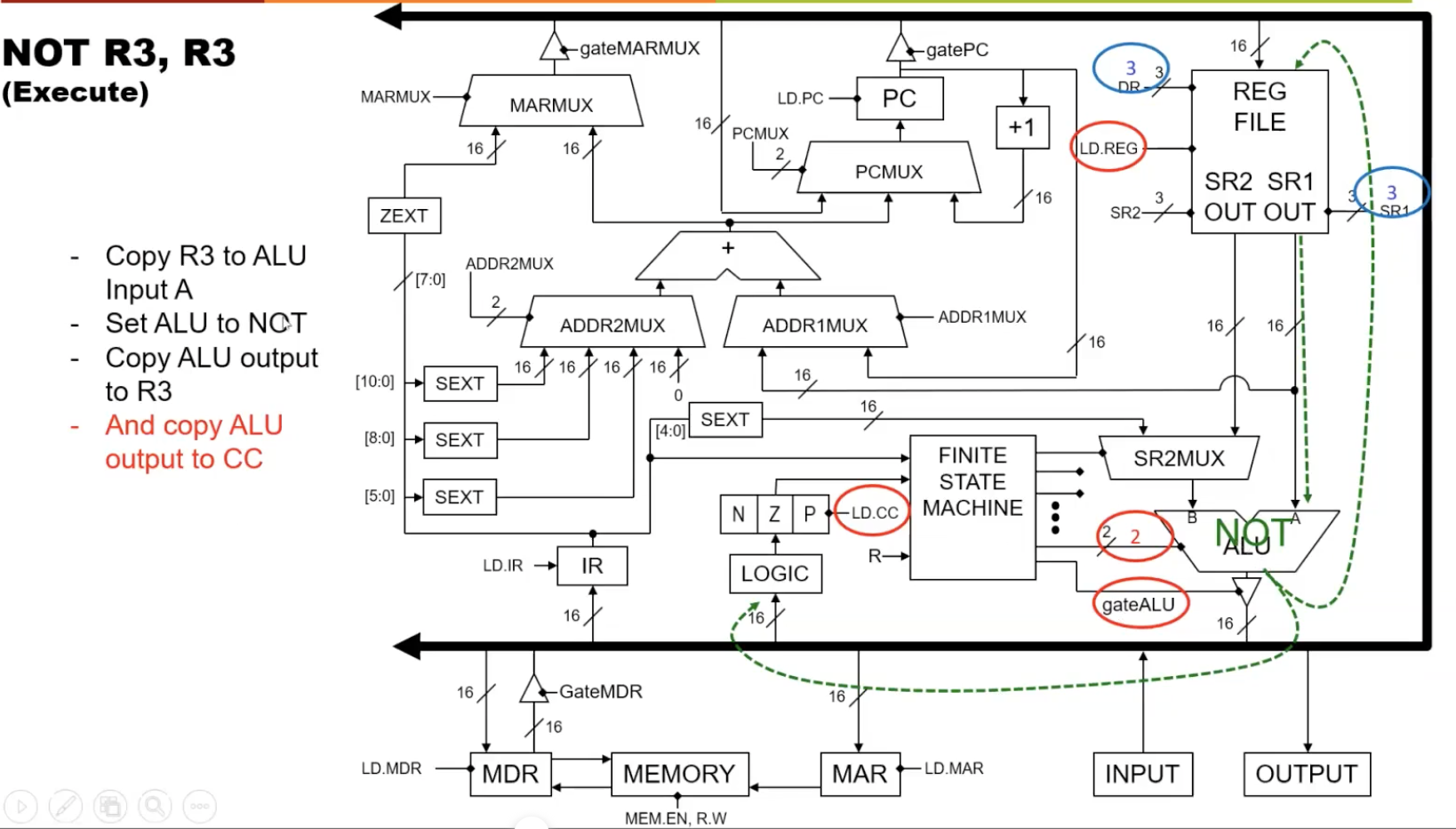
We see from Figure 1 above that the state for NOT is 0b1001, or 9. To execute NOT, the following control signals are turned on: LD.REG, LD.CC, gateALU, SR1MUX=1, ALUK=2. This takes one clock cycle as the Reg File uses the Leader-Follower Flip Flop so it can read as it writes to ALU.
Note that SR1MUX=1 indicates that the value stored in SR1 comes from bit 6-8 in the source register, and ALUK=2 indicates that if the 2-bit ALU selector is set to 2, then the NOT operation will be performed.
Figure 2 shows the execute phase of the NOT state, NOT R3, R3
ADD
There are two flavors of add–register addressing mode or immediate addressing mode, as set/un-set by the 5th bit.
Register addressing mode adds the value stored in Source Register 2 (SR2) to the value in SR1. Example: ADD R1, R2, R3
Immediate addressing mode adds a number literal–an immediate–taken directly from IR to the value stored in SR1. Since the bit size for immediate is 5, which represents a 2’s complement number, its range is -16 to 15. Example: ADD R1, R2, #-3
The state of ADD is 0b0001, or 1, and the control signals sent to datapath by FSM include LD.REG, LD.CC, gateALU, and SR1MUX=1
Note that ALUK is set to 0 by default, and ALUK=0 means “ADD A and B.”
AND
There are also register addressing AND and immediate addressing AND, much like ADD explained above.
The state of AND is 0b0101, or 5, and the control signals sent to datapath by FSM include LD.REG, LD.CC, gateALU, SR1MUX=1, and ALUK=1
Execute State for MOVEMENT Instructions
Movement Instructions have 2 types: transporting data from memory into register (LOAD) and transporting data from register into memory (STORE).
LOAD includes LD, LDR, LDI, and LEA. Discounting LEA, which is its own flavor, there are 3 addressing mode for LOAD instructions.
Store includes ST, STR, STI. There are 3 addressing mode for STORE instructions.
The data operand can be found in one of the three places: one of the 8 registers, directly from IR (literal/immediate data), or from memory.
Effective Address describes the memory location that the instruction uses for its operands, which is from 0 to 65535. The three addressing modes dealing with memory at effective addresses are PC-relative, which does PC + offset, Base + Offset, and Indirect.
Each instruction allows a subset of these addressing modes, which is a common approach in RISC architecture.
…To be continued (stops at 06/08 first lecture 50:39)